Somewhat bizarrely, cables remain a divisive subject within the audio community, the tired old arguments about measured versus audible performance proof that there are many who prefer the evidence of their eyes over the evidence of their ears. But leaving that aside, the evolution of cable quality, performance and construction is a graphic example of audio adaptation. We started by discovering that some cables sounded better than others. Then people started to select existing cables, terminate them and offer them for sale. As the market for and understanding of cables grew, it became practical to start specifying audio-specific designs. That opened the door for high-end offerings but also the hand-built, artisan products we see these days. Now, all but the cheapest cables are audio-dedicated designs or constructions, at least on some level.
You can expect file-replay to follow a similar course, from the laptop connected via USB to a simple DAC, to the emergence of Network replay and dedicated audio network components and linear power supplies. Now we are beginning to see the emergence of audio-dedicated hardware sub-assemblies, critical parts within the digital eco-system itself. While the advent of audio-grade computers is almost certainly a pipe dream, the arrival of key components has coincided with the first major revolution in performance. We may not see complete audio-grade processor units, but the process of selection and adaptation is well under way. The ability to replace compromised componentry with selected or audio-specific elements is absolutely key to maximising musical performance.
Now apply that logic to the Wadax Reference Server. If it sounds better and different, it’s a direct result of doing key aspects of its job so differently: of using different approaches or different (often unique) parts. As a designer/engineer, that means deciding what to keep and what to replace. So the place to start is with what drove those decisions. With that in mind, I decided that the best thing to do was discuss the issue directly with the man who IS Wadax – Javier Guadalajara – and discover in his own words the thought process behind the product and the functional, physical and technological choices that resulted.
RG: I’d like to start by defining the two terms, Server and Renderer. I think there is considerable confusion as to the distinctions between the two and their respective roles. As the question relates directly to the decisions that you made with the Reference Server, perhaps that’s where we should start?

JG: A server is a system that allows you to manage your stored files and streaming services. It provides a user interface, via a Controller, to select and direct items from the library or incoming stream. In turn, the controller sends the file or stream to the Renderer, which converts the USB or Ethernet data into an audio format that can be fed to the convertor. The Renderer itself can be located in the same box as the Server, the DAC or completely separate. So, the designations Server and Renderer refer to different functions and points in the passage of the file or streamed data to the DAC. In practice, the Reference Server can be either a Server (if it sends data to the Renderer in the partner DAC) or a Server/Renderer (if the optional Legacy Output Board is fitted, which provides AES/EBU, S/PDIF and TosLink outputs).
RG: So, if your DAC has no USB or Ethernet input (with the associated rendering capability) then by using a Server/Renderer you can connect its output directly to your DAC’s AES/EBU or S/PDIF inputs?
JG: Exactly. The Renderer is the interface between data streams and the decoding hardware/software in your DAC. In the case of the Reference Server, the optimum performance is achieved when the Server supplies raw data to the Renderer (which is built into the Reference DAC) via our proprietary interface. That interface is the crucial consideration here.
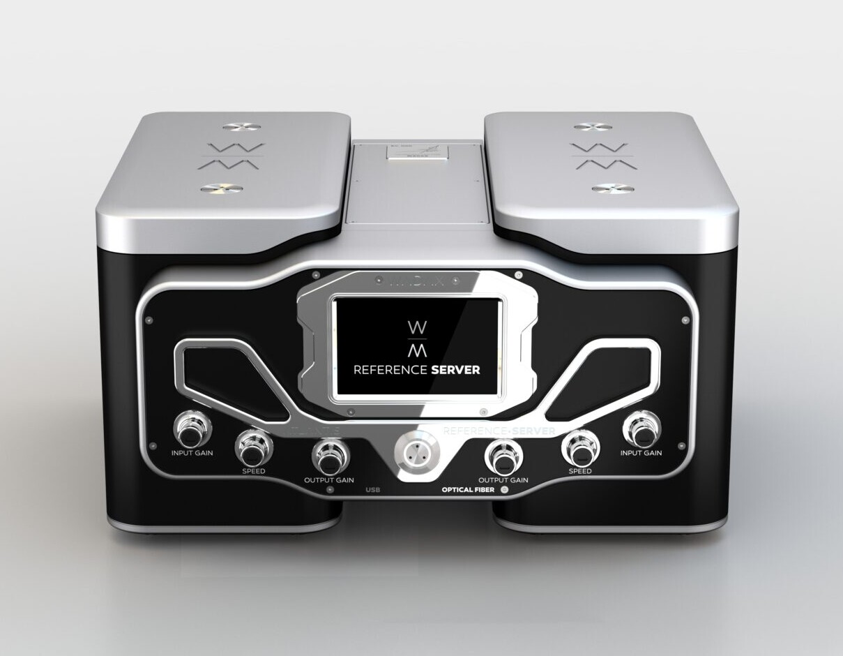
RG: The Reference Server is both massive and massively complex. What makes it different to other servers and why does it need to be so big?
JG: It is different on many levels, both from a hardware perspective and a software perspective. In hardware terms, the Reference Server is based on a similar power supply concept to the Reference DAC. In theory, the power requirements for a Server are very low, but our experience and research shows that in fact you need massive headroom in the power supply if you are going to avoid signal degradation, from noise and other factors. One entire end block of the three-part chassis contains and physically isolates the power supply. That supply is built around three large, independent, custom-built transformers and multiple layers of regulation. When I say large, the combined power output of those three transformers is almost 1kW! We pay particular attention to the rejection of digital noise and the grounding arrangements. So, the size and weight of those components combined with the complex, mechanically isolated and grounded chassis structure means that the Reference Server actually weighs more than many power amps.
The opposite chassis block to the power supply contains the main processor and the unit’s storage bays. Our research and developmental experience all point to the fact that as noise floor drops and performance capability increases, electrical/physical isolation and mechanical grounding become increasingly, almost disproportionately important with digital circuitry. This applies to the Server electronics just as critically to the DAC. That’s why the Server uses such a massive, carefully engineered and segmented chassis. The processor platform itself was chosen with considerable care as we have discovered massive performance differences (in terms of grounding and residual noise issues as well as output accuracy) between units with supposedly similar capabilities. This choice has a significant impact on the integrity of the data stream and therefore, the final musical performance.
This chassis block in the Reference Server provides four storage slots, so you can add up to four 2.5″ SSDs, each of 8TB capacity to accommodate locally stored files. That’s in addition to the 2TB of internal storage that is fitted as standard, giving a current total of 34TB. It also carries the output circuitry and the connections for our Akasa proprietary optical interface. The centre section carries the control circuitry, accommodates the optional Legacy connection board and also allows space for future developments or upgrades. That way the whole system can be updated as and when required, making the reference Server – like the Reference DAC – a future-proof platform that protects our user’s investment.
RG: You have also just launched the Reference PSU, an external power supply unit dedicated to the Reference Server and occupying a similar footprint to the Server itself. What happens to the power supply arrangements when you hook up the external power supply?
JG: That’s correct. We are in the process of building the first batch of Reference PSUs, with delivery scheduled for November (2022). When the Reference PSU is connected to the Server, two things happen. The first is that the onboard power supply is disconnected from the input and processor circuitry and instead is used to run just the display and control elements of the unit, further isolating the audio data from potential internal noise sources. The Reference PSU also provides a massive increase in power supply potential and capacity, all of which is now dedicated to the audio critical data path, local regulation and circuitry. The internal power supply already represents overkill for the Server’s electrical demands. The reference PSU takes that to a whole new level, with an associated increase in isolation from external noise sources and an even lower noise floor. In fact, the low level of noise generated by the Reference PSU is unprecedented: 100nV (from 1Hz to 100kHz) – a reduction of 85% over the already super-quiet on-board supply!
RG: You built the Reference Server around the Roon Core. Once again there seems to be some confusion concerning this subject, many people thinking this refers to a hardware element, making the Reference Server (at least on one level) a ‘dressed up’ Roon Nucleus.
JG: The Roon Core is actually a software solution that offers a unique user interface. That user interface allows you to select files, order play lists and control replay, while also taking advantage of the Roon algorithm that makes programme and listening suggestions based on associated genres, artists/performers and musical styles. It’s a highly sophisticated and constantly developing platform.
The Reference Server is our fifth-generation server product, starting in 2012. Across that developmental history we have looked at and implemented many different solutions, including proprietary software, custom Linux-based systems, J-River… What we learnt was that keeping pace with the latest developments in file formats, partnering equipment, internet radio, user-related recommendation algorithms, they all add complexity, they all need updating and they all need to be trialled across multiple systems and with a massive array of partnering equipment. And you need to repeat that process with each and every development, so the associated effort increases exponentially. Given that server software will never remain static, as users demand more and more features and capability, you end up needing more and more developers, testers and interface managers. Pretty soon, you become a software company rather than a hardware company – and that’s a different business with a different profile. That was not our purpose. We are an analogue and digital hardware engineering and technology company.
In 2014 we first saw a company that promised a roadmap, a plan that covered all of the requirements that we felt were necessary, not just for audiophiles, but for music lovers too. That was Roon.
RG: So Roon meets not just the operational but also the access and convenience requirements.
JG: Exactly. That is combined with excellent technical accuracy and very detailed management of the data path.
RG: The majority of servers on the market use a network connection to the DAC, but you avoid that solution and instead use a direct USB or proprietary optical link. Can you explain the reasons for that choice and the nature of the solutions that you have adopted?
JG: If we ignore wireless options, there are two ways to transfer streaming data in the physical layer – via Ethernet or USB. Our first-generation servers used Ethernet streaming but we quickly realised that this approach suffered from the huge number of network-related service requests generated by other ‘talkers’ connected to the same LAN. Many of these requests were to do with network and network hardware-related issues and especially, where the audio system had no dedicated network, the shared traffic generated significant noise and quality problems. Not only is the quality of network infrastructure incredibly variable, the noise generated by routers, switches, their power supplies and also the Ethernet cable quality can all (and generally do) have a dramatic negative impact on audio performance. Even with audio-grade switches and other network hardware starting to appear, this is still a major problem.
So, in 2015, we decided to concentrate on USB transfer, because it allowed us complete control of the entire data transfer chain – both ends and the cable in between. After all, there really is no better network than no network at all. You will still have to have a network connection to the server – and that network should be as good quality and as quiet as possible. Using optical links between components can be a big help in isolating network noise from the audio system, but we still choose to make that last, critical link between server and DAC via USB, so that we have total control of the transfer environment and complete isolation of the audio data from other ‘talkers’ on the transfer path. Results have demonstrated just how correct that decision was, even if it has involved an enormous amount of work to make USB function properly and as intended.
RG: Apart from the adjustable support platform for the input connector, the USB interface appears perfectly normal – at least from the outside. How does it differ from standard implementations?
JG: It is very different in both electrical and software terms. The circuitry that assembles and drives the data is proprietary and totally different to conventional or off-the-shelf solutions. Not only is this a completely separate, physically independent solution, it actually comprises eight separate circuit boards working in concert at each end of the data path. Most servers use integrated USB drivers that are embedded in the main processor circuitry. A few people use separate boards that piggyback onto the main board, but nobody has come even close to the degree of engineering and execution that we have expended on this aspect of USB transfer.
If you are going to rely on embedded drivers it’s not really surprising that designers migrated to network solutions and Ethernet transfer. But USB offers many significant and obvious advantages – as long as you do it correctly. That’s the challenge. You can add a better power supply or clocking to a standard or even higher-grade USB board, but it’s still essentially a standard USB solution. It’s not a new performance paradigm.
RG: So why does your USB driver demand eight separate boards?
JG: Firstly, because of the extremely strict power supply requirements to achieve and maintain maximum performance: Secondly, because this circuitry is both extremely and specifically sensitive to vibration. If you do not treat each section of the circuit individually, then they start to generate jitter, noise-floor modulation and other side effects that you need to avoid.
RG: So you are isolating elements of the circuit from vibration caused by parts of the circuit itself?
JG: Each board has different levels of isolation from the chassis. There are different requirements in each case, both for relative isolation, one from another and for sensitivity to mechanical isolation.
RG: And is there a difference in the way the data is actually handled?
JG: Yes – a big difference. In fact, this is one of the big breakthroughs we have made, one that separates the Reference Server from everything else. We refer to it as DWC (Digital Waveform Control). Our experience with developing the previous generations of server, as well as our fundamental research programme into digital error mechanisms, is that the transfer function of USB cables varies with type, varies with different lengths of the same type and even between supposedly identical leads of the same type and length – despite maintaining USB 2.0 compliance and data integrity. In other words, despite meeting the USB 2.0 specification and tolerances, all USB cables sound different – and they sound different because variations in construction, materials and geometry produce parasitic capacitance, resistance and inductance values. So every individual cable will have a different transfer function and a different characteristic error mechanism. And don’t forget that this error isn’t just in terms of passing data from the server to the DAC. USB is bi-directional, so the packaging flow is controlled by the feedback loop created by the signal passing from the DAC to the Server, introducing a cumulative timing error.
But what’s really important is that these errors are not data errors. The bit values will be consistent or corrected by the USB receiver. But the spacing of those data points, as long as it is within the tolerances of the data stream, will be incorporated into the signal that is sent to the DAC. These are timing error, either randomly generated or data correlated, that have a very real impact on the arrival time, rate of change or gradient of musical notes.
RG: So the actual data values remain the same, but the signal differs. That seems counter-intuitive?
JG: Yes, but you need to think about the way in which USB works. The data might be digital but the signal that is sent down the cable is analogue: it’s a varying voltage. When the signal reaches the receiver in the DAC, the circuitry has to measure the amplitude of the signal and decide whether (and when) it constitutes a one or a zero. The cable’s electrical characteristics and termination impact the signal it carries and thus its rise and fall in amplitude. In turn that shifts the crossing point at which a data value is registered. The data value remains the same, but its placement – the precise spacing from one sample to the next – is changed. Because that is a time error that happens in the analogue domain, it passes unnoticed. As long as the receiver gets the right number and value of samples, it doesn’t worry about their interval, unless it’s outside the spec for USB transfer. It’s a bit like holding a bag for somebody picking oranges in the supermarket. You know that you need 10 oranges and they are selecting them one at a time. They won’t all arrive at perfect intervals, but unless there’s a really long break between oranges, you won’t wonder why. Ideally, digital receiver circuits have clocking recovery mechanisms that compensate for this, but in practice their performance is far from ideal. Low-frequency phase noise passes unnoticed, plus other contaminating factors.
The problem with these shifts in the interval between samples is that they impact the gradient and timing of transient musical information that is contained in the signal, passed to and decoded by the DAC. And our ear is incredibly sensitive to that information. The errors occurred in the analogue domain and they are preserved when the analogue signal is reconstructed. These shifts in the gradient are a major element in what we perceive as ‘digital’ sound.
RG: So although the signal seems unchanged as far as the digital transfer is concerned, once it is reconstituted as an analogue output, can you see alterations to the spacing and magnitude of the peaks?
JG: No. It’s really difficult to see the effect of this non-linear phase modulation in an analog audio signal with a scope. You will not see any differences in the magnitude of the peaks or the spacing. They will seem normal. Other measurement procedures need to be used. The mechanism by which digital waveform changes enter the analog output is technically called a non-linear phase modulation. The psychoacoustic effects of this are similar to the effects of jitter, but worsened by other side effects: jitter has both a non-deterministic component plus a deterministic one. In this case, the deterministic (data-related) errors have a far higher magnitude than the random ones. Unfortunately these are also the more damaging component.
There is a very interesting example of this. The Atlantis Transport has a facility that allows you to rip a CD directly to a USB stick. We ran an extensive series of experiments, ripping tracks to different sticks and also ripping tracks to the same stick but connecting it via a range of different, identical length cables, often ones as short as a few inches. Examined in a bit-by-bit level, in every case the transfer appeared ‘bit perfect’, but sonically, when the tracks were replayed, there were significant differences in the resulting sound. If ‘bit perfect’ copying of music files actually worked, this wouldn’t be the case. In other words, ‘bit perfect’ refers to data, which is preserved – but NOT the digital waveform, which isn’t. In fact, the whole ‘bit perfect’ approach is based around data values, which for code or software transfer is all that is required. But music files are far more complex than that and we use our most sensitive analytical resource (our hearing) to assess them. It is actually incredibly easy to devise an experiment to demonstrate the erosion of quality caused by digital copying. I think Stereophile even included an example on one of their early test CDs. Yet all the streaming advocates, whether they’re from the record companies, audio manufacturers or end users are happy to ignore this truth. But if ‘bit perfect’ transfer were a reality, all servers would sound exactly the same! ‘Bit perfect’ is an article of faith that no one dares to question. Except that when you do question it, you start to make some real progress in digital music reproduction.
RG: You mentioned the Digital Waveform Control, the three rotary knobs that you see on each side of the Reference Server. The three on the left are for the USB interface and the three on the right for the proprietary Akasa Optical interface. What do they do and how do they solve the issues you’ve just been talking about?
JG: The controls for both the USB and Akasa work in the same way. As we already discussed, we discovered that when you use USB transfer, the rising and falling slopes of the bit stream change. These changes are different for each and every cable. That we expected. What we did not expect is that those changes have sonic consequences. We also tested this with different DACs and USB connections and the impact was always dramatic in sonic terms. So there’s no way that you can set up a USB interface with fixed characteristics and make it both universal and optimal.
Each cable will exhibit a difference in rise time (which in terms of the DWC we designate Speed). So we allow users to compensate for that loss and alter the slope. But there no ideal compensation value, changes in the slope depend on the DAC used. If the slope is too shallow, either to start with or after the DWC compensation, the effect of jitter will be higher. If the compensation results in a slope that is too steep, it will introduce a higher harmonic content, so that high frequency digital harmonics in the bitstream will radiate. The resulting EMI will degrade and pollute the digital and signal ground of the DAC. Given that each DAC has a different construction and design, these values chosen will also need to be different for every DAC used.
The second control (Input Gain) allows you to adjust the crossing point (the point at which a zero registers as a one). Every USB cable (along with the PCB traces and solder connections in its associated circuitry) will have a parasitic inductance and behaves as a voltage divider. Depending on the parasitic resistance level, the terminal voltage will drop and thus the point at which the voltage divider registers an integer change will shift. It acts as a high-pass filter. What we are changing here is the sensitivity of the receiver.
In turn, because the USB link is bi-directional, that will affect the flow control (the return signal that tells the driver when to send more data). In the asynchronous connections used in most audio applications, the receiver controls the arrival rate of the data packages. In terms of the flow rate, the return signal is a feedback loop that impacts on the arrival time of data, adding a compound timing error to the error already caused by the parasitic resistance. The Output Gain control allows you to compensate for this. Of course, if the flow control error becomes too great, the receiver suffers an overload or stalls and the replay will stop. That’s extremely rare, but it also demonstrates the tolerance of error that is accepted within the USB protocols, just to make them work. While those errors are acceptable for most computer applications, they are extremely destructive to high-performance audio.
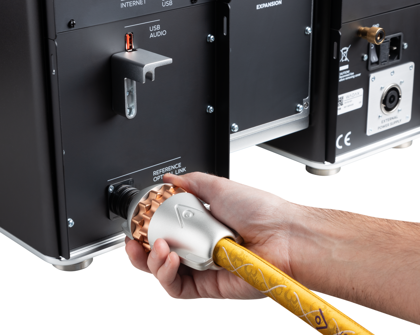
RG: In order to overcome the performance limitations of conventional USB, you developed the Akasa interface, a proprietary optical link. Can you explain your thinking there?
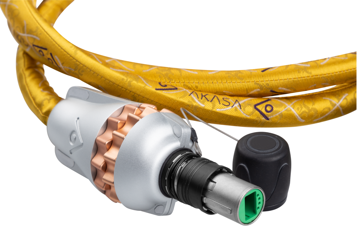
JG: Akasa is our attempt to deliver the performance that USB should have delivered from the start but failed to achieve – at least as a high-quality route for digital music transfer. We took the basic topology of USB but changed those aspects we felt needed to be improved. At the level of the physical layer in the driver and receiver, we are providing an ideal galvanic isolation. Poor galvanic isolation is one of the worst enemies of high-quality digital transfer. If the galvanic isolation isn’t perfect then noise can leak from the ground plane of the processor to the interface. On many off-the-shelf driver and isolation chips, the chip itself is supposed to provide galvanic isolation between two electrical domains. But those domains are incredibly close together and there will be a parasitic capacitance and inductance that allows very low levels of noise to bridge the gap at very high frequencies and in turn, reach the renderer. That noise doesn’t matter for computing applications, but it is critical to audio quality.
RG: So what you are saying is that audio circuitry tends to rely on galvanic isolation, often incorporated in chips and other components, but that this isolation is not an absolute. Levels of isolation that are acceptable for some functionality are not acceptable in audio applications.
JG: That isolation is one of the main objectives for Akasa. The optical interface achieves total galvanic isolation, but the physical layers in the driver and receiver circuitry and the electrical/optical and optical/electrical convertors are completely galvanically isolated too. Because we are controlling the hardware at both ends of the link as well as the choice of the interconnect and terminations, we can significantly narrow the variation in transfer function.
RG: But you also provide DWC for Akasa. Given that you have such tight control over the variables, why is that necessary?
JG: People will still need to use different cable lengths and even with the optical cables, total consistency of termination is impossible so some small variation remains. The added bandwidth of the Akasa interface offers huge benefits in terms of data transfer but also allows for wider-ranging error, so the DWC is still effective, although the Akasa controls have a different scale of operation to the USB ones and are adapted accordingly. To create absolutely identical cables is not possible, so DWC is still a benefit.
So much for the theory: In Part 2 of this review, I’ll be listening to the Reference Server and describing its musical performance. In the meantime, you might want to refresh your memory by looking at the Installation Notes – https://gy8.eu/blog/installation-notes-wadax-atlantis/. It’s going to help when it comes to understanding the influence and complexities of the DWC settings and their relationship to the source material.
- 1
- 2